Sunday, August 24, 2014

Rudder assembly & elevator stiffener, skin prep

With everything for the rudder primed we started squeezing rivets, beginning with the nutplates and reinforcement plates.
 
This is my first installation of a nutplate; they're threaded receivers for screws or bolts of varying sizes that are riveted to the structure of the plane. The screws & bolts are how temporary or removable parts are fastened - think inspection hole covers, instruments, control surface bearing rods, etc.
 Audrey was a big help placing rivets and keeping the shop full of smiles.
 Nice work, Audrey!!
 Some balding guy snuck in to squeeze some rivets...
 But he did ok.

 The first couple attempts I made at riveting the nutplates resulted in some ugly shop heads on the rivets; after while I realized it was a serious bonehead error - I was using rivets 1 size too long!

I was able to remove the nutplates without damaging the spar or reinforcement plates, but after placing the nutplates into a bench vise to remove the crappy rivets with a combination of drilling #40, #30 & twisting with needle nose pliers, I found that I'd removed metal from both nutplates. 2 more errors for the "oops" jar, and 1 more lesson in humility.

I'm planning to rob Peter to pay Paul (seriously, when did that actually happen in the Bible?) and grab some nutplates from the wings to finish the elevators. Eventually I'll have to order more from Aircraft Spruce, but I figure I'll screw something else up before then.
 Above picture = manufactured heads on the thinner material (spar).
 I riveted the rudder horn & nutplate at the bottom with the squeezer for all but the upper, outside-most rivets. Those I had to bang/buck with the rivet gun.
 Next I riveted on the rudder counterbalance rib & skin, the former with the squeezer and the latter with the rivet gun & bucking bar. Even with breaks between build sessions, bucking rivets comes MUCH more easily than it used to!
So about the time I was gaining steam, it was time for another "oops." Did anyone catch it in the last post?
 
That's right, like a moron I primed the OUTSIDE of the counterbalance skin! Grr... At this point I'm going to proceed with riveting it on for practice, and if I find that paint won't cover it later, I'll drill out the rivets and install a new skin.
 With the rivets set, the next step was to fit and install the rudder counterweight. It needed several spots filed slightly to clear the rivet shop heads.

However, once it fit, I realized that the #8 dimple I created in the counterweight rib isn't sufficient. I've ordered a #10 die set to re-dimple the rib, but I'm disappointed that Avery Tools' "deluxe" die set didn't include an essential pair. Moving on...
Brian came over to help for a while, filing channels on the counterweight and marking and cutting (with my lovely wife) on the skin stiffeners for the elevators.
Sunday we match drilled and deburred most of the stiffeners. Tedious work, but fun to be on a new part!
 Erin wasn't too sure about drilling on the skins, but she was game for drilling the nutplate rivet holes to size, stripping blue plastic, marking pieces and (her favorite) hole deburring.
 
Meanwhile I was match-drilling the skins to the stiffeners & working the Scotchbrite wheel.
 We finished about half of the stiffeners & elevator trim plate (E-615).
 Good teamwork, and a productive weekend! New tools are on order - the #10 dimple dies as well as a thin-nose yoke for the rib tip rivets - and I'm debating ordering a longeron (flange) yoke for the rivets on the rudder horn brace. I don't have a bucking bar that will fit, so I either accept using a few pop rivets or bite the bullet and order new tools. We'll see what part of my nature wins.
Time-lapse:
 
 
Empennage: 9 hrs

Sunday, August 17, 2014

Rudder scuffing & priming

I took advantage of the anniversary of my birth to get some help in the shop (also how I got my wife to go camping the first time...go with what works!).
 
I had a surprise helper who hasn't had much interest in the process so far:
 Audrey did a great job scuffing the reinforcement plates, and Erin did almost all of the scuffing & cleaning while I touched up a few edges.
 All rudder parts ready for priming!
 I imagine the parts pile will be quite a bit bigger once we dive into the wings, and might require a full sprayer system...until then I'm sticking with Napa 7220 Self-Etching Primer in a rattle can.
 Anyone see the problem with the above picture?

Oh, and organizing sockets? Actually a matching game for 5 year olds! Seriously, kept her occupied for almost an hour...
 
Empennage: 2 hrs
 
Workshop: 1 hr

Sunday, July 27, 2014

Rudder deburring, dimpling

I took advantage of some time this weekend while the girls are hornswoggling grandma & grandpa out of cookies to work on the rudder.
 
Most holes were already deburred, and I really don't mind that part - my wife has even said it's her favorite task to help with.
 
Edge deburring, on the other hand, is a PITA. This was slightly broken up by the replacement counterbalance skin I ordered to replace the cracked part - 5 days from order to delivery; thanks Vans! Mulligans are much easier on the ground than in the air.
 The skin seemed to fit better than the original, possibly because all rib & spar holes were already drilled & deburred.
 Here's the skin drilled, deburred & beveled where the rudder skins overlap it to provide less ammunition for critics.
Most dimples were easy to reach with the DRDT2, with a few requiring the manual squeezer.
 
The trailing edge of the ribs are extremely tricky to access. Some homebuilders will fabricate their own tools; I don't have the luxury of welding kit, surplus steel stock & gear to grind my own dies, so I found this combo die receiver & slim female die which are worth every penny.
 And the result after a few taps from the 3X rivet gun. If only actually riveting them were this easy....time to buy another tool (don't tell my wife).
 With all edges deburred and dimples complete I prepped the AEX trailing edge wedge and aluminum angle.
(whatthehuh?? The slim trailing edges of control surfaces used to be folded; finding that a skinnier profile offers better handling characteristics, Vans move to a wedge that provides the ideal angle at the trailing edge of the rudder while narrowing to a very thin width at the rear)
 Many builders find that keeping the trailing edge straight for riveting required a guide or guides, such as aluminum angle available in various lengths at Lowe's & Home Depot. I bought 2x 6' lengths.
I clamped the wedge to one piece of angle being sure to keep the edges flush and drilled along the length, moving the 1" Cleco clamps as I went. 
 With one side complete, I flipped & drilled the other angle .Then taking advantage of the wedge being secured, I countersunk all holes on both sides, being careful not to over-countersink which would leave the aluminum too thin & possibly enlarge the holes. Still with me?
 All parts deburred, dimpled & countersunk! Ready for scuffing, cleaning & priming.
I was tired from a long session, so didn't get the counterweight drilled out, which is the final bit of drilling for the rudder. Not sure how much more I'll get done this week, but it's good to know the rudder is nearly ready for riveting.
 
Empennage: 5 hrs


Sunday, July 20, 2014

Horizontal stabilizer stored, Rudder counterbalance skin damaged


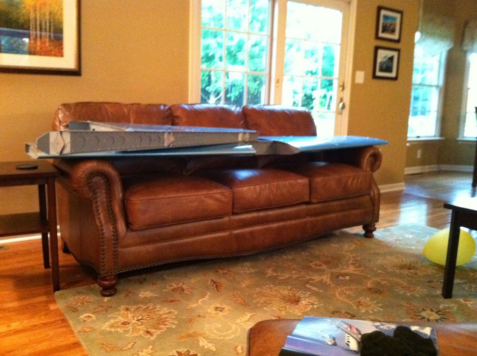
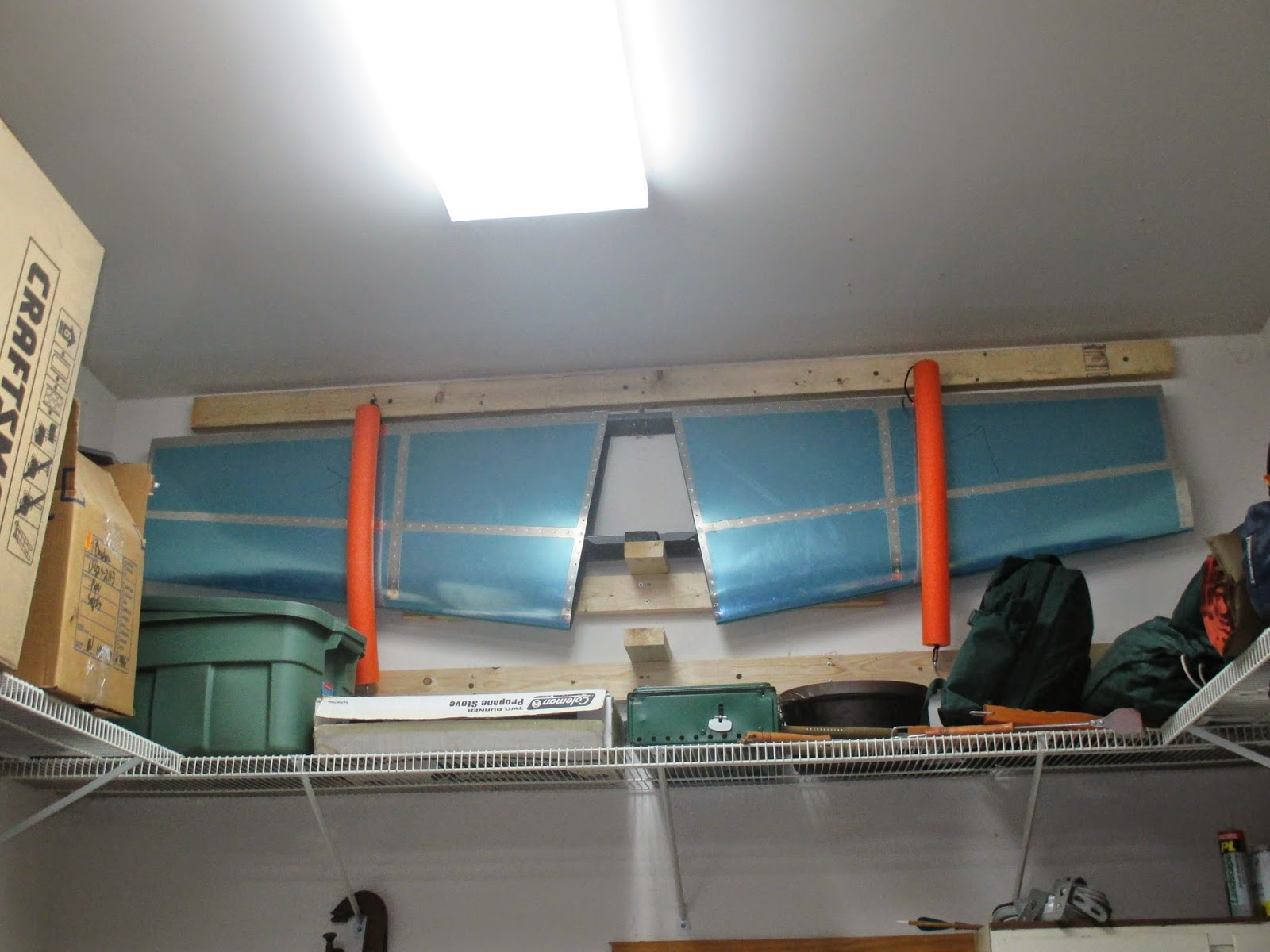
To my wife's relief I removed the HS from its place on our living room couch, took some time this weekend and hung it from the shop wall using 550 cord, eye bolts and swim noodles.


Once the empennage pieces are complete I'll remove the blue vinyl covering and wrap them all for long-term storage in bedsheets to keep out the bugs.

I also spent some time deburring rudder pieces, and found either a deep scratch or small crack in one corner of the R-913 rudder counterbalance skin; more scrap for the heap.

$11.50 for the new part and a cold beer solved that.

 
Empennage: 2 hrs

Sunday, June 29, 2014

SB 14-01-31 Complete, Horizontal Stab Complete! Also rudder dissassembly & deburring

With the girls in Texas herding cattle, I got two long days in on the plane. First up: riveting the horizontal stabilizer.
I'm a slow learner, but after scuffing the front spar repeatedly I realized I could put some scrap cardboard & tape to good use (above, prior to re-taping). The cardboard also served to position the bucking bar centered on the shop head, lessening both my workload and mistakes.
All in all, I only drilled out about half a dozen rivets, and was able to do so without damaging the parts or enlarging any holes. After banging/bucking the forward spar & rib rivets by myself, squeezing the rivets along the edges was a piece of cake.
Soldiers all in a row...
I had to modify (with the consent of Van's Aircraft) the SB forward flange on the left rib, mounting inboard instead of the prescribed outboard placement. Previously it interfered with two of the rivets holding on the new doubler plate, but offsetting to the inboard side eliminated the clearance problem.
Here's a view of the forward side of the doubler plates & reinforcement angles in the middle of the HS. SB 14-01-31 is complete.
Fastest looking workbench I've ever seen...Feels good to see pieces take shape.
While waiting for HS & SB parts this spring I had started on the Rudder construction, proceeding as far as match-drilling all skin holes except the trailing edge. I overcame my nerves and used an angle template like we'd practiced in the SportAir Workshop, drilling half of the holes from each side. This will help the double-flush rivets set properly.
Next I trimmed, fitted & match-drilled the rudder horn brace.
As Van's tries to wean builders off the manual, forcing us to think (and read the prints) for ourselves, I noticed that match drilling the skin-to-horn brace wasn't mentioned. Boom.
Next I fabricated, deburred, clamped and match-drilled the rudder bottom attachment flanges.
One
And two. Time to disassemble & deburr!
On Sunday my buddy Brian from work stopped by to help, so he got stuck removing vinyl & stickers and deburring holes in the skeleton while I deburred the skins. If he comes back after this he must be hooked...
We finished the day by dimpling the 3/32" holes in the skins.
 
Empennage: 12 hrs

Wednesday, June 11, 2014

Rib flange angle modification approved

A note on Service Bulletins (SBs):

Several people with whom I've discussed my recent work adding new reinforcement pieces to the plane questioned my sanity for relying on a company selling an apparently "untested" or "unsafe" product, especially one that can hurl you at the ground from 20,000 ft in the air.

On the contrary, the SB process is proof of the kit maufacturer's ongoing commitment (42 years at this writing) to continue to improve their products and make them safer for pilots. When a defect is discovered, Van's does a thorough engineering review and voluntarily publishes information to mitigate the problem, followed by making repair materials available for existing kits and incorporating the changes into future production kits.

I called Van's regarding the rib flange angle dilemma I faced, describing my proposed solution and outlining the resulting edge-distance issue.

Sterling agreed with my analysis and opined that many RVs would face a similar issue. He said that moving the rib flange inboard was acceptable, and that the edge-distance from the 2 center holes to the flange bend would not affect the safety of the airplane, it was acceptable, and I should "build on."

This problem-solving aspect of the build is one of the most attractive parts for me, and one of the best educational tools of Experimental-Amatuer Built (EAB) aircraft; nerve-wracking and frustrating though it may be...

Empennage: 0.5 hrs

Saturday, June 7, 2014

SB 14-01-31 Rib Flange Angles

After buying a couple 1" C-clamps from the local hardware store I proceeded with fitting and drilling the new rib flange angles as part of SB-14-01-31.
 The right side flange fit well, holes carefully match-drilled using my dremel dentist's drill extension.
Next I removed the rib & flange from the HS and match-drilled the assembly holes to #30.
Upon drilling the left side I ran into a snag. Due to the front spar bend location, the left side doubler plate was riveted close to the existing HS-404 to HS-405 rivet holes. This interfered with the new rib flange angle.
 After considering a few solutions, I discovered that if I moved the flange to the inboard side of the rib I could gain sufficient clearance and maintain edge distance on most of the holes. However the edge distance from the center 2 holes attaching main rib to nose rib are less than 2D (2x diameter) from the bend of the rib flange. I decided to call Van's and see if this is an acceptable fix. As far as I can tell the alternatives all involve replacing an awful lot of aluminum...

Empennage: 4 hrs